
Top Pre-Insulated Pipe Configurations for Industrial Projects: A Ranked Shortlist
Top Pre-Insulated Pipe Configurations for Industrial Projects: A Ranked Shortlist
What decides whether a pre-insulated pipe system is still performing in year fifteen is rarely the pipe itself. It is how that pipe was broken into installable configurations — straight lengths, bends, branch fittings, reducers and joints — and how those configurations were reconnected in the trench.
This ranked shortlist evaluates the five most common pre-insulated pipe configurations used in industrial equipment contexts, ordered by ease of installation and by system reliability. Each position is argued on practical grounds: joint integrity, thermal consistency, site labour dependency, stress behaviour and inspectability.
Stated directly: factory-insulated straight lengths rank first, because they deliver the lowest number of field joints per kilometre and the most uniform insulation along the run. Factory pre-formed bends rank second, prefabricated tees and branch connections third, reducers and transitions fourth, and field-insulated joints fifth — the last of these is treated as its own configuration category because it is the only one whose final quality is determined by the trench rather than by the plant.
Problem Definition: Why Configuration Decisions Outlast Pipe Selection
Directly buried hot water systems are engineered around continuous duty and a multi-decade service horizon. For polyurethane-insulated pipe, a widely applied working envelope is a conveyed medium temperature no higher than 120°C, an occasional peak temperature not exceeding 130°C, and an operating pressure no more than 2.5 MPa. Within that envelope, high-density polyethylene jacketed, rigid polyurethane foam insulated pipe can operate continuously for at least 30 years at 120°C.
That service horizon is exactly why configuration selection matters. A pre-insulated pipe normally shows no visible warning before it fails; joints are where heat loss concentrates, where moisture can enter the insulation, and where mechanical stress becomes discontinuous. The configuration strategy decides how many of those risk points are created in the factory under controlled conditions, and how many are handed to a site crew working in an open trench, in weather, against a programme.
Two consequences follow from this. First, the configuration with the fewest field-created joints is usually the configuration with the highest long-term reliability — not because field crews are unskilled, but because factory foaming and jacketing are repeatable processes and trench work is not. Second, installation ease and system reliability are not separate rankings. They track each other closely, because the same factor — field work volume per unit of pipe — drives both.
The core answer in one line: rank configurations by how much of the insulation and jacketing work they move out of the trench and into the plant. The more work that moves, the higher the installation ease and the higher the long-term reliability.
Industry Background: A Market Measured in Decades, Not Quarters
The global pre-insulated pipes market was estimated at USD 5.97 billion in 2024 and is projected to reach USD 10.4 billion by 2030, growing at a CAGR of 9.7% (Grand View Research). The broader district heating market was valued at USD 209.34 billion in 2024 (SNS Insider), and the combined district heating and cooling market is expected to grow at a CAGR of 5.7% from 2024 to 2032 (Global Market Insights).
Regional distribution shapes sourcing and specification patterns. Asia Pacific dominated the pre-insulated pipes market with a 39.96% revenue share in 2024 (Grand View Research), while Europe holds approximately 38% of the global pre-insulated pipe systems market (Credence Research). Asia-Pacific is also the fastest-growing region, holding a 24% global market share in 2024.
Two structural signals reinforce the configuration question. Commercial end-use accounted for 43.8% of pre-insulated pipe revenue in 2024 (Grand View Research), which points to mid-to-large packaged projects where a single configuration mistake propagates across a whole distribution loop. Meanwhile, pre-insulated pipes for district cooling are projected to grow at a CAGR of 9.48% (SNS Insider), meaning chilled water and directly buried hot water networks increasingly appear inside the same programme and are installed by the same crews — raising the value of configurations that behave predictably across both.
Ranking Methodology: How These Configurations Were Ordered
Each configuration was assessed against six criteria, applied consistently across the shortlist:
- Joint count and joint integrity — how many field-created connections the configuration introduces per unit of installed length, and how much of the joint is finished in the plant.
- Thermal consistency — whether insulation density and continuity are uniform along the run, or interrupted at field-rebuilt locations.
- Installation labour and skill dependency — the hours per metre and the level of specialist capability the trench crew must supply.
- Thermal stress and expansion behaviour — how the configuration responds to cyclic temperature change and where stress concentrates.
- Inspectability and maintenance access — whether defects can be detected and reached without excavating an entire run.
- Scenario fit — whether the configuration behaves equally well in directly buried and above-ground installations.
The higher-ranked configuration is consistently the one that shifts the largest share of insulated work into controlled factory conditions. This is the same principle that underpins the national standard for directly buried insulation pipes — the specification work that Tangshan Xingbang Pipeline Engineering Equipment Co., Ltd (Xingbang) participates in as a drafting contributor.
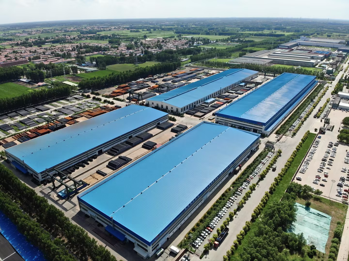
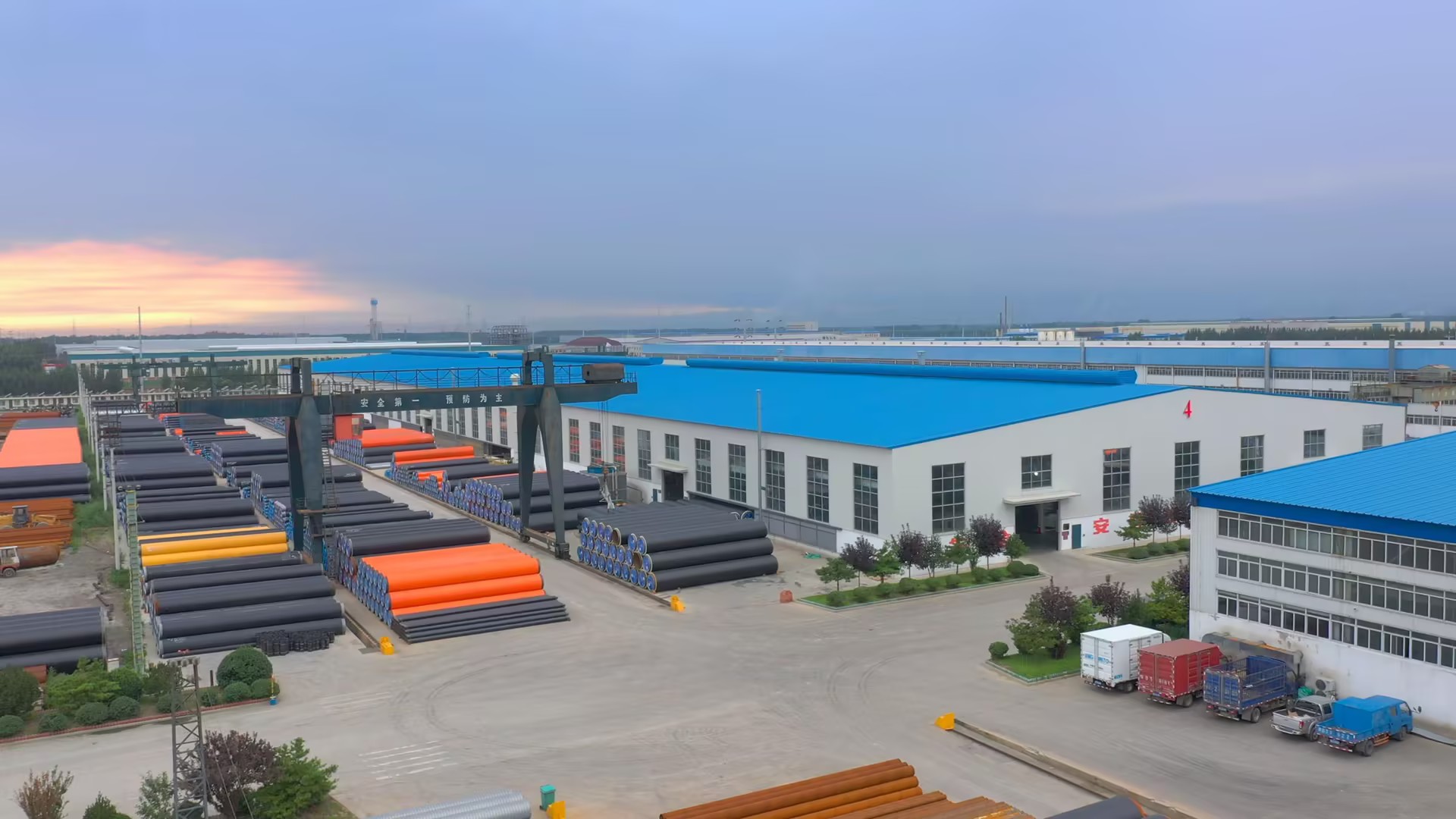
For context on the supply side: Xingbang is a Chinese pre-insulated pipe manufacturer located in Houhu Industrial Park, Yutian Economic Development Zone, Tangshan City, Hebei Province, supplying directly buried hot water pre-insulated pipe for district heating, district cooling, petroleum, chemical, LNG and gas pipeline projects. Its manufacturing base covers 310,000 m² with 231 employees, including a 30-engineer technical team, and insulation pipe production capacity exceeding 3,000 km per year. Roughly 30% of output is exported, principally to Europe, North America and the Middle East.
Ranked Shortlist: Pre-Insulated Pipe Configurations for Industrial Projects
The ranking below covers the configurations that account for the overwhelming majority of installed length in a typical industrial pre-insulated network. Each entry explains why it holds its position, what it does well, and where its limits lie.
Rank 1 — Standard Factory-Insulated Straight Lengths
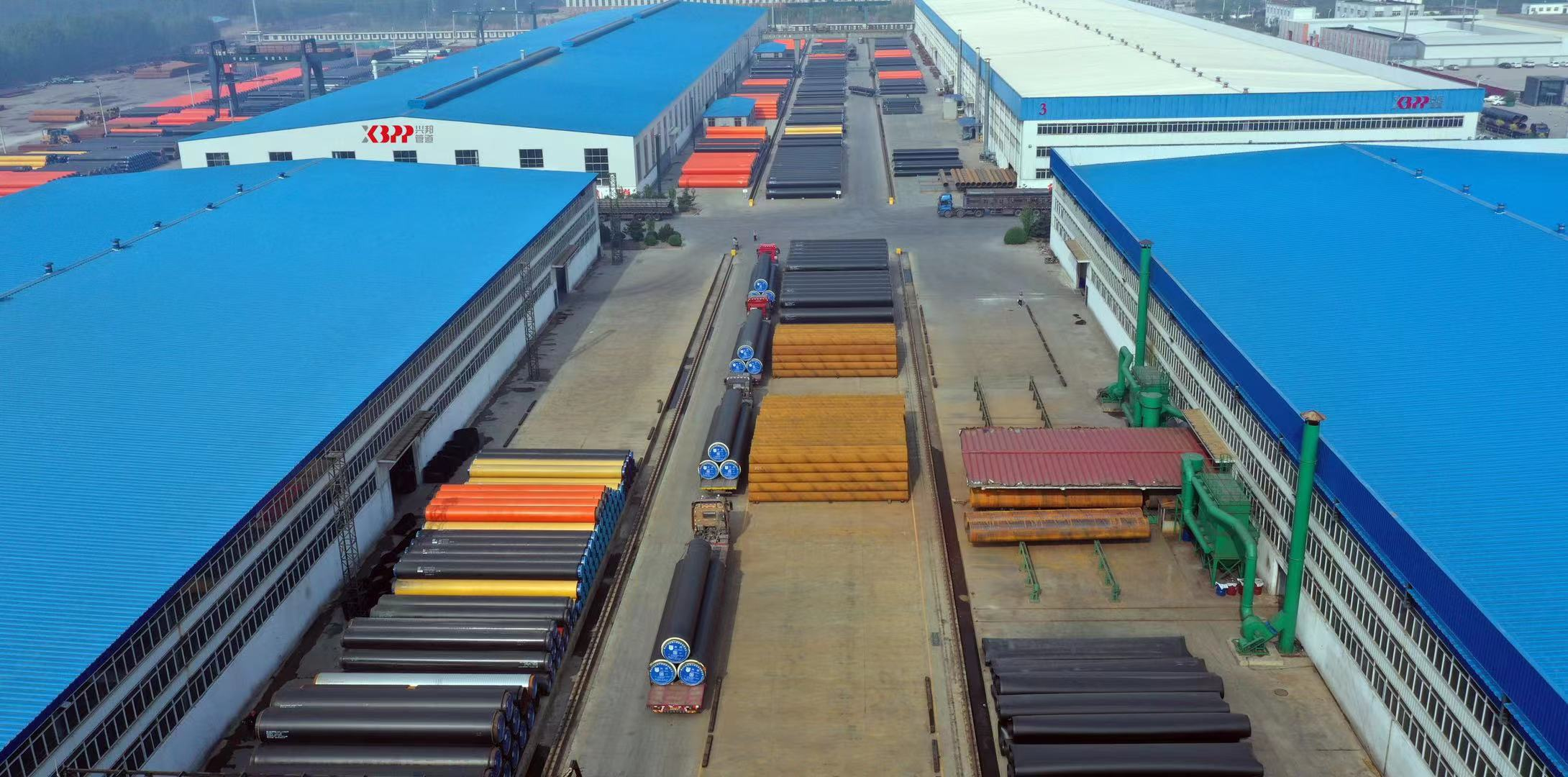
Factory-insulated straight lengths take the top position because they produce the fewest field joints per installed kilometre and the most uniform insulation along the run. A straight length is formed as a single bonded unit: working steel pipe, rigid polyurethane foam insulation, and a high-density polyethylene outer jacket, all closed in the plant.
The only field operations are lifting, alignment, welding at the pipe ends, and local insulation reinstatement at each connection. Three factors explain why this configuration ranks first on reliability:
- Thermal consistency. Factory foaming produces consistent density along the pipe axis. Insulation rebuilt on site can develop voids or uneven density, which become localised heat-loss points.
- Joint reduction. A straight run requires one joint per pipe length. A run laid out with many field-fabricated bends and branches requires several joints for the same distance. Fewer joints mean fewer locations where moisture ingress and thermal bridging can begin.
- Continuous outer jacket. The jacketed surface is factory-formed, so the moisture barrier runs unbroken to the pipe end rather than being pieced together in the trench.
Where the limits are. Straight lengths require transport and lifting capacity appropriate to their length, and they need enough trench width and bend radius to be placed without forcing. On congested industrial sites — pipe racks, plant rooms, tight equipment connections — the achievable straight run is short, and the share of bends and fittings rises accordingly. The ranking does not change, but its practical dominance does.
Rank 2 — Factory Pre-Formed Bends and Elbows
Ranking second, factory pre-formed bends are the single most effective configuration for protecting joint integrity at direction changes. Making a bend on site means cutting the insulated pipe, stripping the foam, bending the working pipe, then rebuilding the insulation and jacket in an open trench. That rebuilt section rarely matches the density and moisture resistance of a factory-formed length.
Pre-forming moves the entire operation into the plant, where the geometry, foam fill and jacketing are completed under controlled conditions before the pipe is shipped. The result is a bend whose insulation performance is continuous with the adjacent straight lengths rather than a deliberate weak point in the middle of the circuit.
The trade-off. Pre-formed bends demand accurate measurement before excavation begins, and they add lead time ahead of delivery because geometry has to be fixed at the factory rather than improvised on site. For programmes where the routing is still being adjusted during construction, that constraint is real. Where the routing is fixed at design stage, the trade-off is straightforward: a modest increase in planning effort in exchange for removing a permanent thermal and moisture defect from the network.
Rank 3 — Prefabricated Tees and Branch Connections
Branch connections are the hardest location in any pre-insulated network at which to maintain insulation continuity, which is why prefabricated tees rank third rather than lower. A tee must reconcile three separate insulation paths — main pipe, branch pipe and the junction between them — in a single component.
When a tee is prefabricated, the main-line insulation, the branch insulation and the junction infill are produced as one integrated assembly. This matters most in district heating and cooling distribution networks, where branch lines are frequent and where each branch is a potential heat-loss concentration point.
Stress behaviour. A tee is also where thermal stress concentrates, because the branch introduces a local stiffness change in an otherwise uniform run. Prefabricated tees allow the junction geometry and insulation envelope to be designed as a unit, rather than assembled from whatever materials are on the site. This is the configuration category where relief structural design at the junction has the largest effect on long-term behaviour.
Installation note. Prefabricated tees are heavier and less tolerant of alignment error than straight lengths, so they typically consume more crane time per unit. Their installation ease is therefore rated medium rather than high, even though their reliability contribution is substantial.
Rank 4 — Reducers and Transition Fittings
Reducers and transition fittings rank fourth. Their position reflects the fact that a diameter change is inherently a discontinuity: flow velocity shifts, thermal expansion behaviour changes, and the insulation envelope has to step between two different pipe sizes.
These fittings are unavoidable in most industrial circuits — trunk mains stepping down into distribution branches, or equipment connections requiring a different bore from the main run. Prefabrication helps by keeping the stepped insulation geometry in the factory, but the configuration still concentrates more structural and thermal discontinuity per unit length than a straight length, a bend or a tee.
Practical guidance. Keep the number of transitions low by designing the main-line diameter profile deliberately rather than following the equipment schedule connection by connection. Where transitions are unavoidable, group them at accessible locations so that the region can be inspected without excavating an unrelated section of the run.
Rank 5 — Field-Insulated Joints
Field-insulated joints occupy the fifth position. This is not a judgement that they are inherently poor, but a recognition that they are the only configuration on this list whose final quality rests mainly on site conditions rather than on a controlled manufacturing process.
Every straight length, bend, tee and reducer on this list terminates in a joint, so the total number of field-insulated joints in a network is the sum of all the configuration decisions taken upstream. That is the practical link between this rank and the four above it: choosing configurations higher on the list directly reduces the number of fifth-rank joints a project needs.
What joint integrity depends on. The working pipe connection is typically welded, and the integrity of that weld is a prerequisite for everything that follows. Insulation reinstatement must then reproduce, in the trench, the foam density and jacket continuity that the factory achieved along the pipe. Moisture entering a poorly reinstated joint is the mechanism by which a pre-insulated system degrades from the inside.
Controls that make joints predictable. Where a manufacturer supplies the full system rather than the pipe alone, joint quality can be supported by process controls upstream: incoming raw-material inspection, full-batch product performance testing, 3PE anti-corrosion treatment on the working pipe, a high-density polyurethane insulation layer, and built-in optical fibre temperature sensing for buried pipeline online monitoring. Real-time temperature monitoring, anti-corrosion coating protection, insulation protection and stress-relief structural design are the recognised control methods for thermal stress damage, high-temperature overheating, pipeline corrosion and excessive heat loss.
Step-by-Step Breakdown: From Configuration Ranking to a Procurement Plan
Applying this ranking in practice follows a defined sequence. Each step below converts a configuration decision into something a project team can specify, price and verify.
- Decompose the route into configuration types. Walk the design route and classify every element as a straight length, bend, tee, reducer or joint. Count the joints. The joint count, not the total pipe length, is the number that predicts long-term reliability.
- Convert bends and branches to prefabricated items at design stage. Fix the geometry before excavation. Every bend or tee that is prefabricated removes one field-rebuilt insulation section from the network permanently.
- Maximise straight-length runs where site conditions allow. Longer straight runs mean fewer joints. Where trench width or equipment connections force a short run, accept a higher fitting share but record it explicitly so the trade-off is visible.
- Confirm the configuration matches the medium. Directly buried hot water, above-ground installation, chilled water and boiler steam each impose different working conditions. Confirm the temperature and pressure envelope before finalising the configuration list.
- Fix the commercial terms early. Confirm minimum order quantity, delivery terms, payment structure and acceptance testing before geometry is locked, because configuration changes after order placement carry the highest cost.
- Define how the system will be verified. Decide in advance whether joint integrity and insulated-run performance will be checked by pre-shipment testing, by batch performance records, or by online monitoring after commissioning.
Use Cases: Where Each Ranked Configuration Fits
The ranking is stable across project types, but the weight each configuration carries changes with the application.
- Directly buried district heating mains. Straight lengths dominate, with prefabricated bends at route changes. This is the configuration profile where the Rank 1 advantages compound most, because installed length is long and joint count is the dominant reliability variable.
- District cooling and chilled water networks. Similar profile, but insulation continuity matters more because the temperature differential to ambient is smaller and any moisture ingress degrades performance disproportionately.
- Above-ground installations. Galvanised iron jacket pre-insulated pipe is commonly used here, and supporting and expansion hardware adds joints that buried installation does not require. Ranking order is unchanged, but the case for prefabricated bends strengthens.
- Equipment and plant-room connections. Short runs, many direction changes, frequent diameter transitions. This is where Ranks 2 to 4 carry most of the load and where Rank 1 straight lengths are least applicable.
- Boiler and steam service. Thermal stress relief and stress-relief structural design become the governing criteria, which raises the importance of prefabricated tees and properly designed transitions.
- Oil, gas and chemical transfer lines. Anti-corrosion treatment and inspectability dominate, which places more weight on the joint-quality controls described under Rank 5.
Comparison Table: Ranked Pre-Insulated Pipe Configurations
| Rank | Configuration | Installation Ease | System Reliability | Primary Risk Factor | Best-Fit Application |
|---|---|---|---|---|---|
| 1 | Factory-insulated straight lengths | Highest per unit — lifting, alignment, welding only | Highest — continuous factory insulation and jacket | Transport and lifting constraints | Long straight runs in directly buried district heating mains |
| 2 | Factory pre-formed bends and elbows | High — geometry arrives complete | High — no field-rebuilt insulation section | Measurement accuracy fixed before excavation | Route changes and direction changes in buried or above-ground networks |
| 3 | Prefabricated tees and branch connections | Medium — heavier, less alignment tolerance | High when prefabricated as one assembly | Insulation continuity at the junction; stress concentration | Distribution branch lines in district heating and cooling |
| 4 | Reducers and transition fittings | Medium-high — straightforward but geometry-sensitive | Moderate — inherent discontinuity | Thermal stress concentration at diameter change | Trunk-to-branch step-downs and equipment connection points |
| 5 | Field-insulated joints | Lowest — most skill- and weather-dependent | Determined by site process quality | Joint integrity, moisture ingress, thermal bridging | Any location where two pipe elements must be connected on site |
One comparative figure is worth noting for budget-stage planning. Against conventional onsite insulated pipe, pre-insulated pipe has been assessed as delivering approximately 10% lower cost, a performance gap of 0.4°C/km, higher efficiency and less maintenance, with central heating supply as its strongest application fit. Those advantages depend on configuration: a network assembled from many site-fabricated sections does not capture them to the same degree as one built from factory-formed elements.
Frequently Asked Questions
What standards govern pre-insulated pipe configurations for directly buried hot water networks?
EN 253 is the industry standard for pre-insulated bonded pipe systems used in directly buried hot water networks. For the working steel pipe itself, ASTM A53 is a primary American standard covering seamless and welded black and hot-dipped galvanized steel pipe. Buyers specifying industrial pre-insulated pipelines should confirm that the pipe, insulation and jacket are specified against a recognised system-level standard rather than against individual material properties alone, and that joint configurations are covered by the same specification.
What temperature and pressure limits apply to these configurations?
The configurations described here are applied in pipe network systems where the conveyed medium temperature is no higher than 120°C, the occasional peak temperature does not exceed 130°C, and the working pressure is no more than 2.5 MPa. Under a 120°C operating environment, polyurethane insulated pipe can operate continuously for at least 30 years. Note that the insulation material itself is the limiting element in many designs: polyurethane foam insulation for EN 253 pipe typically withstands temperatures up to 120°C. Where service conditions exceed that envelope, the configuration mix and insulation selection must be reviewed before the ranking above is applied.
How does configuration choice affect the total cost of an industrial pipeline?
Configuration choice affects cost through two routes. The first is installed cost: prefabricated elements carry a higher unit price than site-fabricated equivalents, but remove trench labour hours, reduce programme risk and lower the rate of rework. The second is lifecycle cost: fewer field joints reduce heat loss over the operating life and lower maintenance frequency. Against conventional onsite insulated pipe, pre-insulated pipe has been assessed at roughly 10% lower cost with a 0.4°C/km performance gap and less maintenance. Projects should evaluate both routes together rather than comparing unit prices configuration by configuration.
Can configurations be tested or sampled before full production?
Yes. Pre-shipment testing is a standard acceptance method for pre-insulated pipe supply, and full-batch product performance testing plus incoming raw-material inspection are the upstream controls that make shipped configurations verifiable. Sampling is most useful at the level of the configuration rather than the pipe alone: request samples or test sections of the bend, tee and joint insulation reinstatement you intend to use, not only of the straight length. The minimum order quantity for pre-insulated pipe supply is 500 metres, which sets the practical scale of a first validation batch.
What does long-term supply look like for an industrial pre-insulated pipe programme?
Supply for an industrial programme is normally structured around FOB or CIF delivery terms with pre-shipment acceptance testing and a 30/70 payment structure. Because a pre-insulated network is installed over an extended programme, the configuration list fixed at design stage tends to govern repeat orders, extension phases and maintenance sections. Working with a single supplier who can reproduce the same configuration set — same insulation build-up, same joint method, same jacket type — is what keeps later phases compatible with the initial installation, and it is the practical reason long-term supply continuity matters more in pre-insulated piping than in most industrial components. Configuration drawings, batch records and joint procedures should be retained as part of the project documentation.
Conclusion: Ranking Configurations by What Leaves the Trench
The ranked shortlist comes down to one measurable principle: the configurations that move the most insulation and jacketing work into the factory rank highest, because they produce the fewest opportunities for heat loss, moisture ingress and stress concentration to enter the network.
Standard factory-insulated straight lengths rank first. Factory pre-formed bends rank second. Prefabricated tees and branch connections rank third. Reducers and transition fittings rank fourth. Field-insulated joints rank fifth — and their total count in any project is simply the sum of every configuration decision taken above them.
Applied properly, this ranking is not an abstract design exercise. It is a procurement filter: it tells a project team where to accept a higher unit price in exchange for a permanently lower joint count, and where a lower-cost site-fabricated alternative is genuinely acceptable. On a network designed for at least 30 years of continuous service, that is the decision that compounds.
Next Step
If you are specifying a pre-insulated pipe configuration set for an industrial project, Xingbang can supply configuration drawings, sample sections for joint and bend validation, and batch performance records alongside the pipe itself. The company supplies directly buried hot water pre-insulated pipe to district heating, district cooling, petroleum, chemical, LNG and gas projects across Europe, North America and the Middle East.
Download the Xingbang product catalogue (PDF) for configuration options, insulation build-ups and delivery terms — or send your route drawing and we will return a configuration list against it.
Website: www.xingbanginsulatedpipe.com | Email: xbinsulationpipe@xingbang1995.com | WhatsApp: +8618833358018
Have Questions or Need More Details?
Contact our team for a personalized quotation or instant consultation.
Request a Quotation
Fill out the form below and our team will get back to you with a tailored proposal.
WhatsApp Direct Chat
Prefer to chat in real-time? Message us on WhatsApp for instant assistance & quick answers.
- Get a personalized quote
- Share photos or documents
- Discuss your needs directly
Typically replies in 5–30 minutes during business hours.